

How To Draw Arduino Circuit Diagram
Tabular array of content:
- Starting a new project
- Arranging the environement
- Building a excursion
- Editing properties
- Exporting a circuit
Starting a new project
Before starting a projection in Fritzing, yous will demand to build an electronic circuit in the existent globe and make sure it works properly. You will then most rebuilt the circuit in Fritzing.
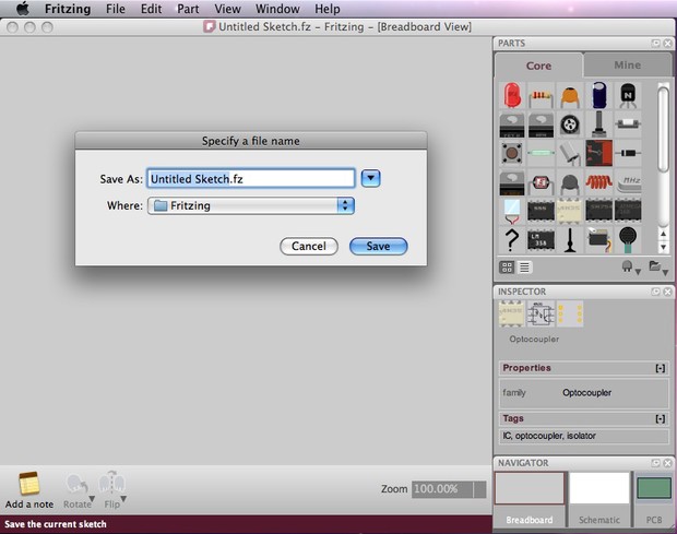
Let's start by opening Fritzing, naming and saving our projection. Saving a project is highly recommended at start and every now and then while working, since Fritzing is nevertheless Alpha and unfortunately might sometimes crash...
- From the Fritzing menu bar, select File > Salvage As...
- Specify a proper name and location for the project and click Relieve.
Arranging the environment
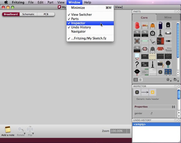
Earlier we get-go working, we might desire to arrange the environment according to our needs and preferences.
- From the Fritzing Menu Bar, select Window > and marker the palette windows you lot would like to see in the environs.
- Elevate & drop palette windows anywhere in the environment and notice how windows rearrange, combine or float.
- Choose the breadboard view in the Navigator, in case it is not already selected.
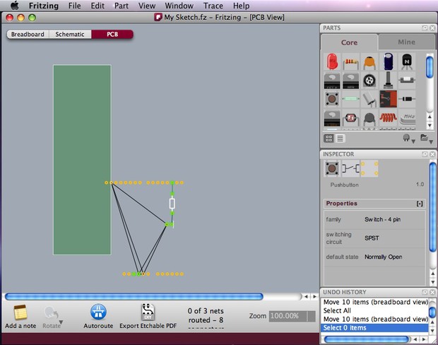
Building a circuit
Make sure your excursion in the real earth works properly. Then rebuild your circuit in Fritzing following these guidelines:
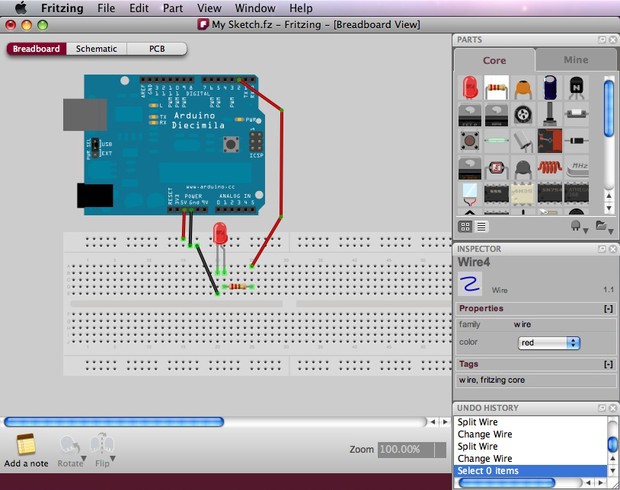
- Drag & drib an Arduino from the Parts palette window to the Project View.
- Do the aforementioned with a breadboard and all other parts of your excursion. If you cannot find a part in the library, use the Mystery Function (icon looks like a qustion marking - ?). The Mystery Office will let you quickly define a new part and its connectors (through the Inspector).
- You can arrange parts by selecting, dragging and dropping, or by using the functions in the carte bar, located under Office.
- To delete a part, just select and press BACKSPACE.
- Click & elevate the Arduino +5V connector. This should create a wire. Drop the wire on one of the breadboard'southward connectors. The connection is confirmed by a pocket-sized green circle or square.
- Connect all parts until the circuit looks exactly like your circuit in the real earth. Notice that connectors that are non properly connected are painted cherry.
- If you click and agree on a connector, Fritzing will highlight all equipotential connectors. This tin can really be useful if you want to see the whole prepare of connections attached to this item connection.
- Y'all can bend wires by calculation bend-points. Just elevate them out of a wire.
- Select the schematic and pcb tabs to watch or edit your circuit in these views.
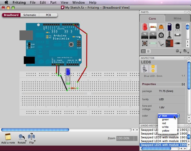
Editing properties
Now that we have all parts connected, let's meet how we can modify the properties of each part.
- Select any of your circuit'south parts and take a look at the Part Inspector palette window.
- Click on the part'due south proper noun and rename it. This is useful when you want to distinguish between similar parts.
- Try besides to change other backdrop.
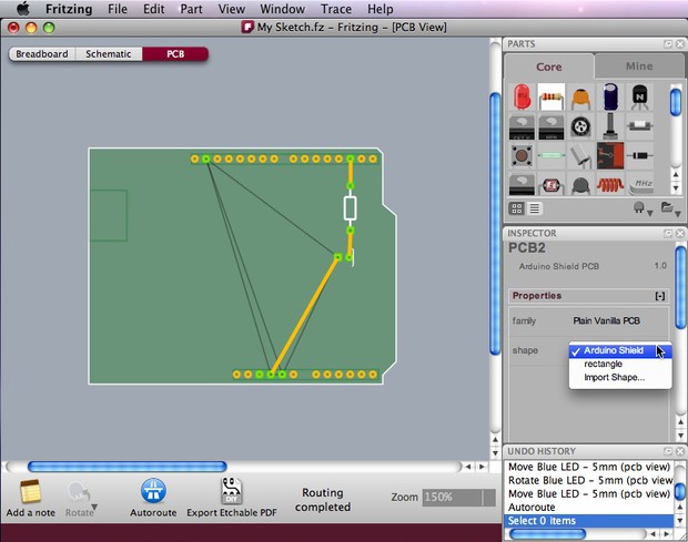
Y'all can as well modify properties of parts in the PCB View. The lath's shape could exist inverse to an Arduino shield, a resizable rectangle or a custom shape.
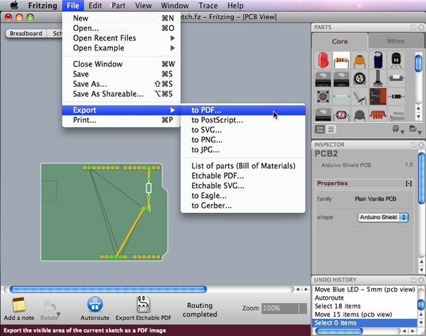
Exporting a circuit
After finishing edifice the circuit, save your project. You might desire to export your circuit as an image file or PDF.
- Select the desired Project View to exist exported (breadboard,schematic or pcb).
- From the Fritzing menu bar, select File > Export > and the desired format.
Now that we went through the basic workflow, lets move on and learn how to create custom parts and how to design a PCB.

Source: https://fritzing.org/learning/tutorials/building-circuit
Posted by: josephphisecome.blogspot.com
0 Response to "How To Draw Arduino Circuit Diagram"
Post a Comment